Troubleshooting the Front Brake
Pad Sensor Warning Light
By Paul Waterloo
The brake pad warning light is designed to come on when the front brakes wear down to about 25% left on the pads. It is triggered by an insert in the pads that has two wires attached. The wiring and pad is part of a ground loop that starts at the instrument cluster, goes through both brake pads and to ground. Once this path is broken, the brake pad warning light comes on.
If you want to remove this function from your car and never see this light again, follow this procedure.
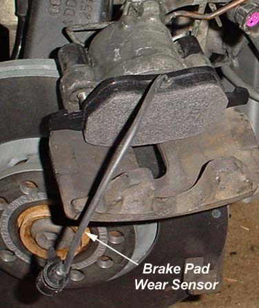
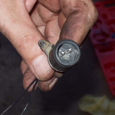
Single caliper piston and inboard brake pad with brake pad
wear sensor integrated into the pad.
When installing new pads with built in brake pad wear sensors, just hook them back up when performing the brake job and you'll be on your way!
However, many aftermarket brake pad sets do not have the sensors installed. Therefore, the old sensors must be cut off the old pads, the wire insulation stripped, the wires twisted together, wrap them in electrical tape, fold them over and tie wrap the whole thing up. Then plug it into the car side harness. This maintains continuity in the circuit, which will prevent the brake pad wear sensor light from coming on.
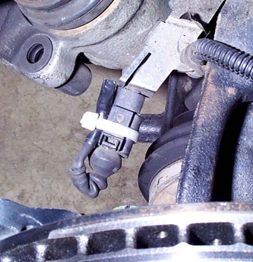
Brake sensor wiring cut off old pad, shorted out, taped up and tie wrapped in place. This will maintain circuit continuity so the brake pad warning light won't come on.
Photo courtesy of Jeff Bipes.
In the case that this was done, but the light still comes on, it needs to be troubleshot. The following outlines how to troubleshoot the bad connection. Remember, the circuit should be a short circuit. The brake pad warning light comes on when the circuit opens.
Troubleshooting the Brake Pad Warning Light
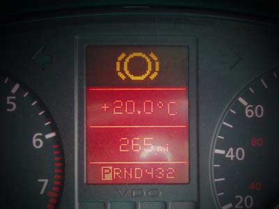
The brake pad warning light circuit is a ground path loop. When this ground path is interrupted (open circuited, like turning a light switch off), the brake pad warning light (K32 in image) comes on.
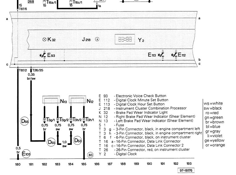
Brake pad wear sensor circuit. Schematic shown is for 97-99 model years.
The brake pad wear circuit starts from the back of the instrument cluster (pin 25 on red 26 pin connector), through the firewall somewhere, to T3g, pin 1 (3 pin connector back left of engine compartment) to N13, which is the brake pad wear indicator, left. It then goes back to T3g, pin 2 and over to T3h, pin 2 to N12, the right brake pad wear indicator. Then back through T3h, pin 1 which is then connected to chassis ground at point 83. 83 is ground connection 1, in right front wiring harness.
Follow that path, it goes from the sensing circuit which is at 12 VDC to ground at point 83 which is chassis ground. When this circuit is interrupted, the light comes on. Easy? Yes, it really is.
The wiring is most likely all in place and in good shape. The problem most likely lies in the plug in connector at the brake pads. Do the following first:
Unplug the connector and on the side with the shorted wires (that use to be attached to the pads) take a resistance reading across the two pins. This should be less than 1 ohm resistance. If greater than 1 ohm, remove the tape and remake the connection. Ensure it is less than 1 ohm.
Clean the pin and socket connections on each side of the connector. This is most likely where your problem is. Use contact cleaner from Radio Shack with a small brush.
Make up the connection, start the car with your foot on the brake, then put it in gear and check for the light (will only light up with the car in gear). If it went away, you've found your bad connection. If not, take resistance readings to ground as outlined below.
Ensure you clean the contacts of the sensor connector on both male and female side. This is most likely the problem. Follow directions above. Resistance readings across the two shown contacts should be less than 1 ohm. If not, remake connections.
So how to troubleshoot? Pretty easy. Find three pin connectors T3g and T3h in the engine compartment. I believe this connector is down at the bottom front of engine compartment, forward of the wheels on each side. The belly pan would have to be removed first.
Perform a continuity check from the brake pad side of pin 1 on T3g to the brake pad side of T3h pin 1. You disconnect these connectors, hook up a multimeter on the resistance range, and you should have 1 ohm or less for continuity.
But if your brake pad wear light is on, it will probably be an open circuit (greater than 2000 ohms, most likely infinity).
Measure the continuity across each of the brake pad wear indicators as shown in the image. One will most likely be shorted (continuity) and the other will be open circuited. Find the one that is open circuited and repair as required by shorting the brake pad wear sensor wires. You probably put on aftermarket pads that didn't have them and now the old ones need to be cut and twisted together to create the ground path.
If these circuits tested good, then take a resistance reading from the ground side of T3h pin 1 to a known ground location. You should have continuity (short circuit). If not, troubleshoot and repair wiring.
If that tests good, pull the instrument cluster and check continuity from T26 pin 25 to T3g pin 1. There should be continuity. If not, repair wiring.
Want to skip all these tests at first? Find T3g pin 1, and connect the instrument cluster side to ground with a jumper wire. Turn the car on, did the brake pad warning light go off? If so, you know the problem is down stream. You could reconnect it and do the same from T3h pin 2. If the light is still off, you know the problem is down stream of that point.